Understanding the Basics of Circuit Analysis
Understanding the Basics of Circuit Analysis
Circuit analysis is the mathematical analysis of any electrical circuit. In other words, it is the calculation of unknown elements within a circuit, such as the voltage or current. This aims to solve problems in electric circuits using an established set of equations. Two popular methods for circuit analyses are the node voltage method and the mesh current method.
This blog post will explain circuit analysis basics, such as the concepts, laws, methods, and steps involved in analyzing circuits. We will also provide some examples and resources to help you learn and practice circuit analysis.
What is a Circuit?
Before we dive into the discussion on circuit analysis, let us first define a circuit or an electronic circuit. An electronic circuit is a system composed of components such as resistors, transistors, capacitors, inductors, diodes, and many more, connected by wires through which electric current can flow. Building circuits is about using electricity to build useful devices for our everyday lives.

There are two types of circuits: series and parallel. A series circuit is a circuit where the components are connected end-to-end in a single path. A parallel circuit is one where the parts are connected in multiple paths. The type of circuit affects how the voltage and current are distributed among the members.
What are the Electrical Quantities?
To analyze circuits, we need to understand the electrical quantities, such as voltage, current, resistance, power, etc. Different units and symbols measure these quantities.
-
Voltage:
Voltage measures the electric potential difference between two points in a circuit. It is also known as electromotive force (EMF) or potential. It is measured in volts (V) and denoted by V or E.
-
Current
Current is the measure of electric charge flowing through a point in a circuit per unit of time. It is also known as amperage or intensity. It is measured in amperes (A) and denoted by I.
-
Resistance:
Resistance measures how much a component opposes the flow of electric current through it. It is also known as impedance or ohmic value. It is measured in ohms (Ω) and denoted by R or Z.
-
Power:
Power measures how much work an electric current does in a unit of time. It is also known as wattage or energy. It is measured in watts (W) and denoted by P or W.
What are the Electrical Relationships?
To analyze circuits, we also need to understand the electrical relationships, such as Ohm’s and Kirchhoff’s laws. These relationships are based on physical principles and can be expressed by mathematical equations.
- Ohm’s law:
Ohm’s law states that the voltage across a resistor is directly proportional to its current. Mathematically, it can be expressed as:
V=IR
where V is the voltage, I is the current, and R is the resistance.
Ohm’s law can be used to find any one of these quantities if the other two are known.
- Kirchhoff’s laws:
Kirchhoff’s laws are two fundamental laws that govern the conservation of charge and energy in a circuit. They are:
- Kirchhoff’s current law (KCL):
KCL states that the sum of currents entering a node (or junction) is equal to the sum of currents leaving it. Mathematically, it can be expressed as:
∑Iin=∑Iout
Where Iin, and Iout, are the currents entering and leaving the node, respectively. KCL can be used to find unknown currents in a circuit.
- Kirchhoff’s voltage law (KVL):
KVL states that the sum of voltages around any closed loop in a circuit is zero. Mathematically, it can be expressed as:
∑V=0
Where V are the voltage around the loop, with a positive sign for voltage drops and a negative sign for voltage rises. KVL can be used to find unknown voltages in a circuit.
What are the Circuit Analysis Methods?
We can use various methods to analyze circuits that apply these electrical relationships to simplify and solve circuits. Two popular methods for circuit analyses are:
- Node voltage method:
The node voltage method of analysis solves for unknown voltages at circuit nodes in terms of a system of KCL equations.
- Mesh current method:
The mesh current method of analysis solves for unknown currents in circuit loops in terms of a system of KVL equations.
How to Analyze Circuits?
To analyze circuits, we can follow these general steps:
- Identify the type of circuit (series or parallel) and the electrical quantities to be found (voltage, current, resistance, power, etc.).
- Choose a suitable analysis method (node voltage or mesh current) and label the circuit elements accordingly (nodes, loops, voltages, currents, etc.).
- Apply the electrical relationships (Ohm’s law, Kirchhoff’s laws, etc.) to write equations for the unknown quantities.
- Solve the system of equations using algebraic or matrix methods.
- Check the solution for consistency and accuracy.
Examples and Resources for Circuit Analysis
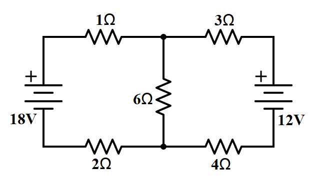
To illustrate, let us look at an example of circuit analysis using the node voltage method.
We want to find the node voltages V1 and V2 in this circuit. We can follow these steps:
- Identify the type of circuit and the electrical quantities to be found. This is a parallel circuit with two nodes and three branches. We want to find the node voltages V1 and V2.
- Choose a suitable method of analysis and label the circuit elements accordingly. We choose the node voltage method and label the nodes as V1 and V2. We also label the reference node as 0V and the branch currents as I1, I2, and I3.
- Apply the electrical relationships to write equations for the unknown quantities. We apply KCL to nodes V1 and V2 and Ohm’s law to the resistors. We get:
I1+I2=I3
2V1−10+4V1=2
6V2+4V2−V1=0
- Solve the system of equations using algebraic or matrix methods. We can use substitution or elimination to solve for V1 and V2. We get:
V1=8V
V2=12V
- Check the solution for consistency and accuracy. We can plug in the values of V1 and V2 into the original equations and see if they are satisfied. We can also check if the values make sense physically.
For more examples and resources on circuit analysis, you can check out these links:
- How to Analyze Circuits: A blog post that explains how to analyze circuits using various methods and examples.
- Circuit Analysis: A video series that teaches how to analyze circuits using various methods and examples.
- Circuit Analysis: An online course covering circuit analysis basics using various methods and examples.
Frequently Asked Questions (FAQs)
1. What is circuit analysis?
- Circuit analysis is the process of studying electrical circuits to understand how currents and voltages behave within them.
2. Why is circuit analysis important in electrical engineering?
- Circuit analysis is fundamental for designing, troubleshooting, and optimizing electrical circuits, which are prevalent in various applications.
3. What is an electrical circuit?
- An electrical circuit is a closed loop or path through which electric current flows, typically consisting of components like resistors, capacitors, and inductors.
4. What are the basic components of a circuit?
- Basic components include voltage sources, current sources, resistors, capacitors, inductors, and wires.
5. What is Ohm’s Law, and how is it used in circuit analysis?
- Ohm’s Law states that voltage (V) equals current (I) multiplied by resistance (R), expressed as V = IR. It’s used to calculate voltage, current, or resistance in circuits.
6. How do you analyze series and parallel circuits?
- In series circuits, resistances add up, while in parallel circuits, the reciprocal of the total resistance is the sum of the reciprocals of individual resistances.
7. What are Kirchhoff’s laws, and how are they applied in circuit analysis?
- Kirchhoff’s laws include the Current Law (KCL) and the Voltage Law (KVL), which are used to analyze complex circuits by conserving current and voltage.
8. What is nodal analysis, and when is it used in circuit analysis?
- Nodal analysis is a technique used to analyze circuits by finding the voltage at each node (connection point) and determining the currents flowing between them.
9. What is mesh analysis, and when is it used in circuit analysis?
- Mesh analysis is a technique for analyzing circuits by dividing them into meshes (closed loops) and solving for the current in each mesh.
10. How are capacitors and inductors analyzed in circuits?
- Capacitors and inductors are analyzed using differential equations that describe their voltage-current relationships over time.
11. What is transient analysis in circuit analysis?
- Transient analysis examines how circuits behave during the time it takes for them to reach a steady-state condition after a change in input.
12. What is frequency domain analysis in circuit analysis?
- Frequency domain analysis focuses on how circuits respond to sinusoidal inputs, helping analyze circuits' behavior at specific frequencies.
13. Can software tools be used for circuit analysis?
- Yes, software like SPICE (Simulation Program with Integrated Circuit Emphasis) is commonly used for simulating and analyzing complex circuits.
14. What are some real-world applications of circuit analysis?
- Circuit analysis is used in designing electronic devices, power distribution systems, telecommunications networks, and various electrical systems.
15. Where can I learn more about circuit analysis and electrical engineering?
- You can study circuit analysis through electrical engineering courses, textbooks, online resources, and by experimenting with electronic circuits and simulation software.