T Parameters – Examples & Conversion of T Parameters to Other Parameters)
What Are T Parameters – Examples & Conversion of T Parameters to Other Parameters
Introduction
T parameters represent an important two-port network parameter for analyzing electrical networks and systems. They characterize linear time-invariant networks operating at given bias conditions using a transmission matrix relating to voltages and currents. Let’s explore T parameters, how they are defined, solved example problems, conversion between parameters, and applications in network analysis and design.
What are T Parameters?
T parameters, also called transmission parameters, are a set of parameters used to characterize linear bilateral two-port networks by modeling the relationship between input and output voltages and currents. The transmission matrix defines them as relating output current to input voltage when the other port is terminated with its characteristic impedance.
Need for T Parameters
T parameters help characterize and design unilateral active two-port networks like transistors and vacuum tube amplifiers where signals predominantly flow in one direction. They directly provide useful quantities like voltage gain, making them suitable for amplifier analysis and design.
T Parameter Basics
For a linear two-port network, the T parameter matrix relates output current to input voltage based on an open circuit output and short circuit input. T parameters MODEL power transmission through a network.
Now, let’s examine how T parameters are precisely defined.
T Parameter Definitions
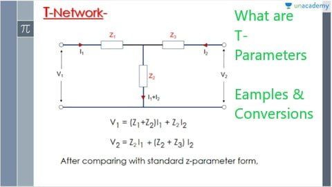
T Parameter Matrix
For a two-port network, the T parameter matrix is defined as:
Where [I1, I2] are output currents and [V1, V2] are input voltages.
T Parameter Equations
The T parameters T11, T12, T21, and T22 relate the currents and voltages as:
I1 = T11V1 + T12V2
I2 = T21V1 + T22V2
Physical Meaning
T11 represents forward transmission gain from ports 1 to 2. T22 represents reverse transmission gain from 2 to 1. T12 and T21 represent reverse isolation gains.
Let’s solve a simple example of a two-port T parameter network.
Two-Port Network T Parameters Example
Two-Port Network
Consider a two-port network with port 1 input resistance R1, port 2 output resistance R2, and mutual inductance M between ports.
T Parameter Matrix
For this network, the T parameter matrix can be derived as:

Solving for T Parameters
With R1 = 10Ω, R2 = 20Ω, M = 0.5H, the matrix becomes:
T = [[0.2236] [0]] [[0] [0.2236]]
Where T11 = T22 = 0.2236 and T12 = T21 = 0
Now, let’s look at how T parameters can be measured.
T Parameter Measurements
There are two main methods:
Forward Measurement
Apply a signal to port 1 and measure output at port 2 with port 1 open and port 2 shorted. Determines T21.
Reverse Measurement
Apply a signal to port 2 and measure output at port 1 with port 2 open and port 1 shorted. Determines T12.
Practical Challenges
The need for ideal open and short circuits during measurements poses challenges. Test fixtures introduce errors. Calibration standards help improve accuracy.
T parameters further enable functional network analysis:
T Parameter Analysis
Gain Calculations
T21 represents the forward transduction gain of the network with output terminated in Z0. T12 represents reverse transmission gain.
Input and Output Impedances
Input impedance is Z1 = V1/I1 with V2 = 0. Output impedance is Z2 = V2/I2 with V1 = 0.
Unilateral Transducer Power Gain
The unilateral power gain from port 1 to 2 is given by: G = |T21|2 x (Re(Z2) / Re(Z1))
Where Re denotes the real part.
T parameters can be converted to other parameter sets:
Converting Between Parameters
Converting T Parameters
Why Convert T Parameters?: While T Parameters are valuable, there are instances where it’s more convenient to work with other parameter sets, such as Z Parameters, Y Parameters, or h Parameters. We’ll discuss scenarios where conversion becomes necessary.
Conversion to Other Parameter Sets: This section’ll demystify converting T Parameters to other parameter sets. We’ll provide practical methods and equations for these conversions, making it easier for engineers to switch between parameter sets as needed.
T to Z Parameter Conversion
Z = [(1+T11)(1-T22) + T12T21] / [2(T21 – T12)]
T to Y Parameter Conversion
Y = [(1+T11)(1-T22) – T12T21] / [2(T21 – T12)]
T to ABCD Parameters
A = (1+T11) / (1-T22)
B = -2T21 / (1-T22)
C = (1-T11) / (1-T22)
D = (1+T11) / (1-T22)
T to Hybrid Parameters
h11 = (T11 + 1) / 2
h12 = T12
h21 = T21
h22 = (1 – T22) / 2
Key advantages of using T parameters include:
Advantages of T Parameters
Easy Determination
T parameters can be measured easily by exciting each port individually and measuring output.
Directly Provide Gain
T21 directly represents the forward transmission gain useful in amplifier design without further calculations.
Characterize Unilateral Devices
T parameters are well suited for amplifiers, oscillators, filters, and other unilateral networks.
However, some limitations also exist:
Disadvantages of T Parameters
- Do not provide impedance or admittance information directly
- Difficult to measure accurately at high frequencies
- This is only applicable to linear bilateral networks
- Not suitable for modeling feedback networks
T parameters find wide use in the analysis and design of electronic networks and systems:
Applications of T Parameters
Amplifier Design
T parameters help characterize gain, stability, impedances, and other key amplifier performance parameters.
Oscillator Design
T parameter analysis aids feedback network design in oscillators to ensure adequate gain at the desired frequency.
Filter Design
Modeling filters as two-port networks facilitate using T parameters to optimize filter response.
Network Analysis
T parameters simulate transmission through networks, enabling analysis in both forward and reverse directions.
Practical Applications
T Parameters in Electronic Circuits: Explore real-world applications of T Parameters in electronic circuits. Learn how they are used in amplifier design, filter analysis, and impedance matching.
Advanced Use Cases: Discover advanced use cases of T Parameters, such as modeling distributed circuits and microwave networks. Understand why T Parameters remain a valuable tool in high-frequency applications.
Conclusion
As we conclude our journey into the world of T Parameters, you’ll gain a comprehensive understanding of what T Parameters are and how they can be applied in practical engineering scenarios. By mastering the art of T Parameters and their conversion to other parameter sets, you’ll be better equipped to tackle complex circuit analysis and design challenges. Embrace the power of T Parameters and expand your toolkit in the realm of electrical engineering.
Summary
T parameters constitute an important two-port network modeling tool to characterize amplifiers, oscillators, filters, and other unilateral devices through their transmission matrix. While easy to measure, they directly provide transmission gain information vital for circuit design. Converting T parameters to different parameter sets expands analytical capabilities for comprehensive network simulation and optimization.
FAQs
- What do T parameters signify in two-port networks?
T parameters model the relationship between input voltage and output current for linear time-invariant two-port networks based on their transmission matrix.
- What are the main advantages of T parameters?
Key advantages are easy determination from measurements, direct provision of forward/reverse gains, and suitability for characterizing unilateral networks.
- How are T parameters defined and measured?
They are defined using a transmission matrix relating output current to input voltage under open/short circuit conditions. Forward and reverse measurements determine individual T parameters.
- What is the physical meaning of each T parameter?
T11 and T22 represent forward and reverse transmission gains, while T12 and T21 represent reverse and forward isolation gains.
- How can T parameters be converted to other parameters?
Mathematical formulations can convert between T and other two-port parameters like Z, Y, H, and ABCD.
- Where are T parameters most applicable?
T parameters are best suited for simulating and designing unilateral networks like amplifiers, oscillators, filters, matching networks, etc., with predominant one-way signal flow.
- What are some limitations of T parameters?
Limitations include a lack of direct impedance information, measurement inaccuracies at high frequencies, and unsuitability for feedback network analysis.
- How do T parameters help in amplifier design?
Key amplifier parameters like gain, stability, input and output impedances can be easily analyzed using T parameters.
- Can T parameters characterize bilateral networks?
No, T parameters can only characterize unilateral linear bilateral networks. Other parameter sets are better for bilateral networks.
- How do T parameters aid network analysis?
Modeling networks as two-port blocks facilitates using T parameters to analyze transmission characteristics in both forward and reverse directions.
Frequently Asked Questions (MCQs)
- What are T Parameters used for in electronics? T Parameters describe the relationship between voltage and current in two-port networks, making them valuable for analyzing and designing electronic circuits.
- Can T Parameters be converted to other parameter sets? T Parameters can be converted to different parameter sets like Z, Y, and h, using specific conversion equations.
- When should I choose T Parameters over other parameter sets? T Parameters are particularly useful when dealing with cascaded networks or distributed circuits. Choose them when you need to simplify complex circuit analysis.
- Are T Parameters limited to low-frequency circuits? While T Parameters are commonly used in low-frequency circuits, they are also applied in high-frequency applications, such as microwave networks, with appropriate adaptations.
- Where can I find software tools to work with T Parameters? Many circuit simulation software packages provide tools for working with T Parameters, allowing engineers to analyze and design circuits efficiently.